Last Friday I took apart my old Spyder2 monitor colorimeter to see how it worked. Apparently it uses 7 colored filters with a light sensor behind each one, by comparing the amount of light absorbed by each filter it can determine the color on screen. I was fascinated by how it worked so I decided to take a shot at making my own.
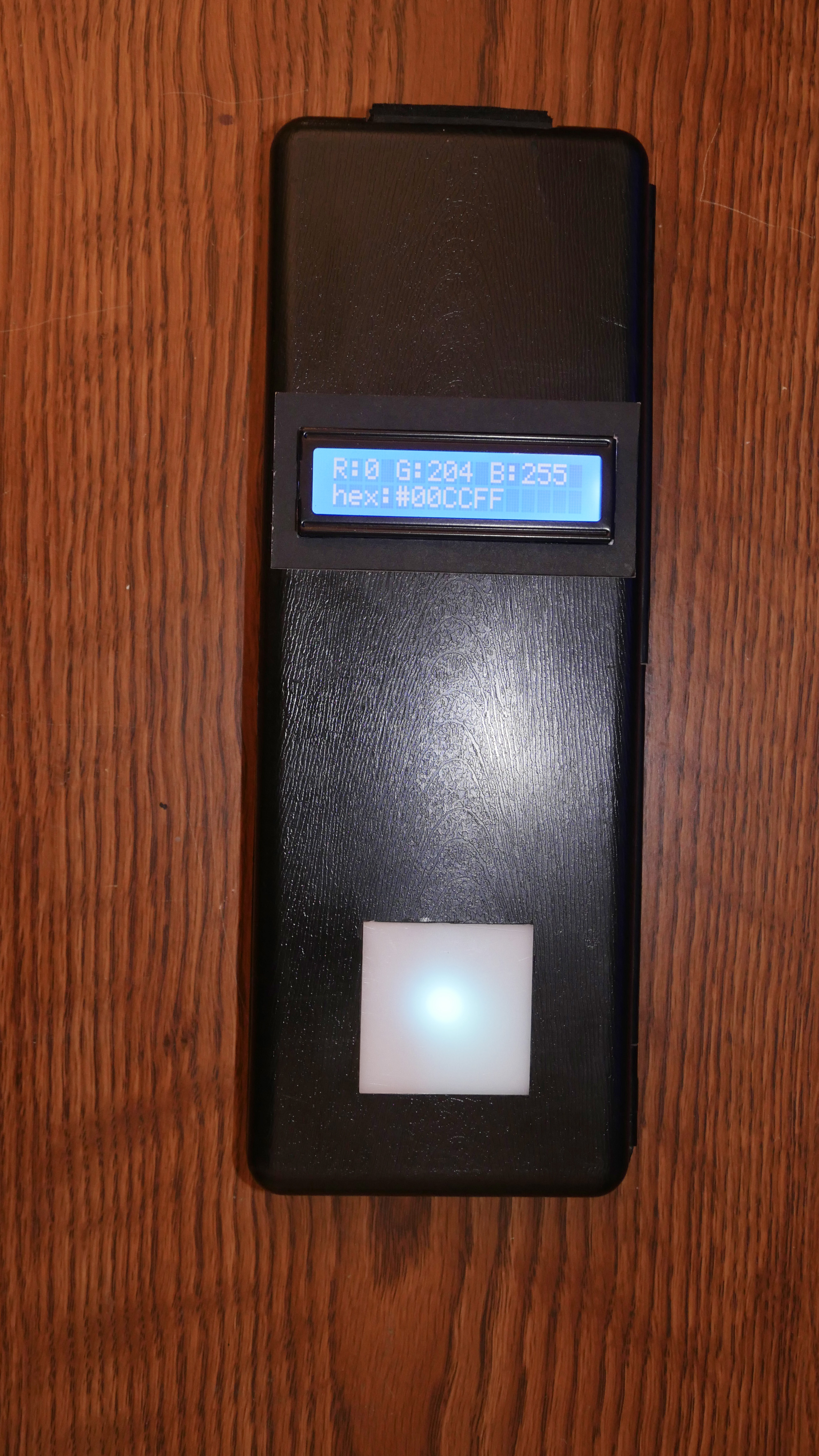
Here’s a peak at the finished product
##Constraints:
- Only use components from around the house
- Finish it in roughly a weekend
- Ideally small enough to be hand held
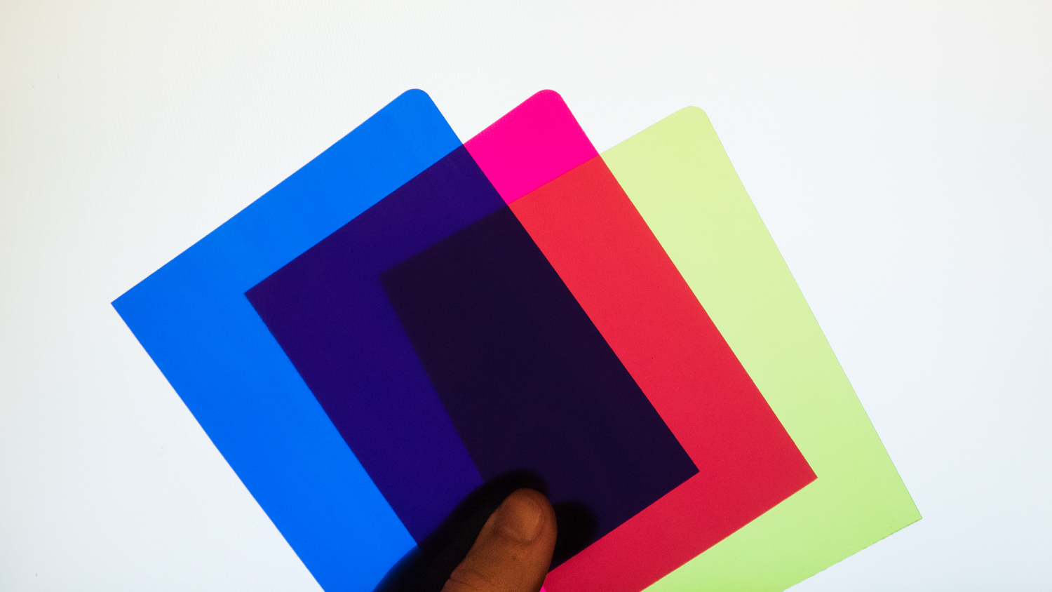
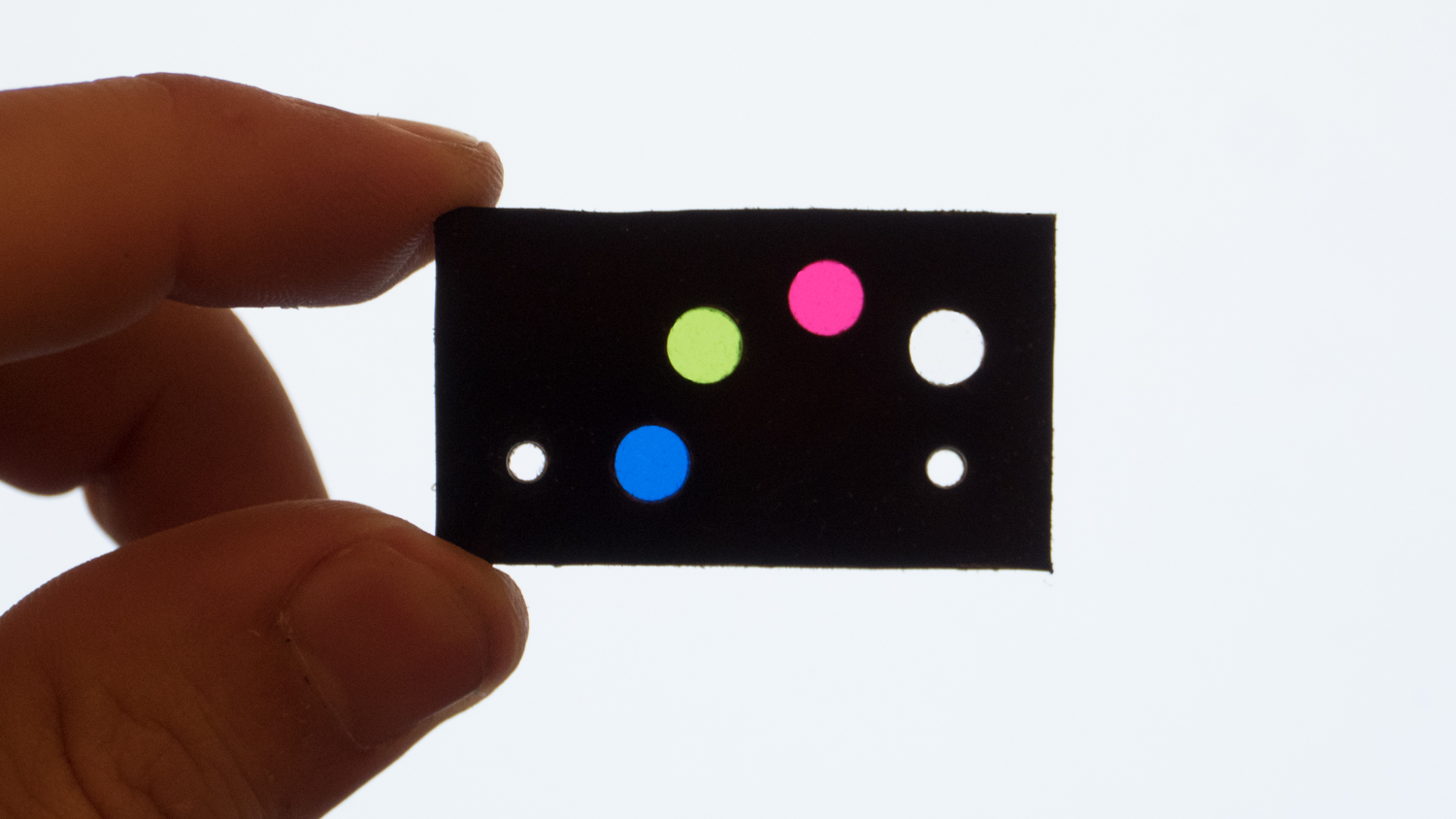
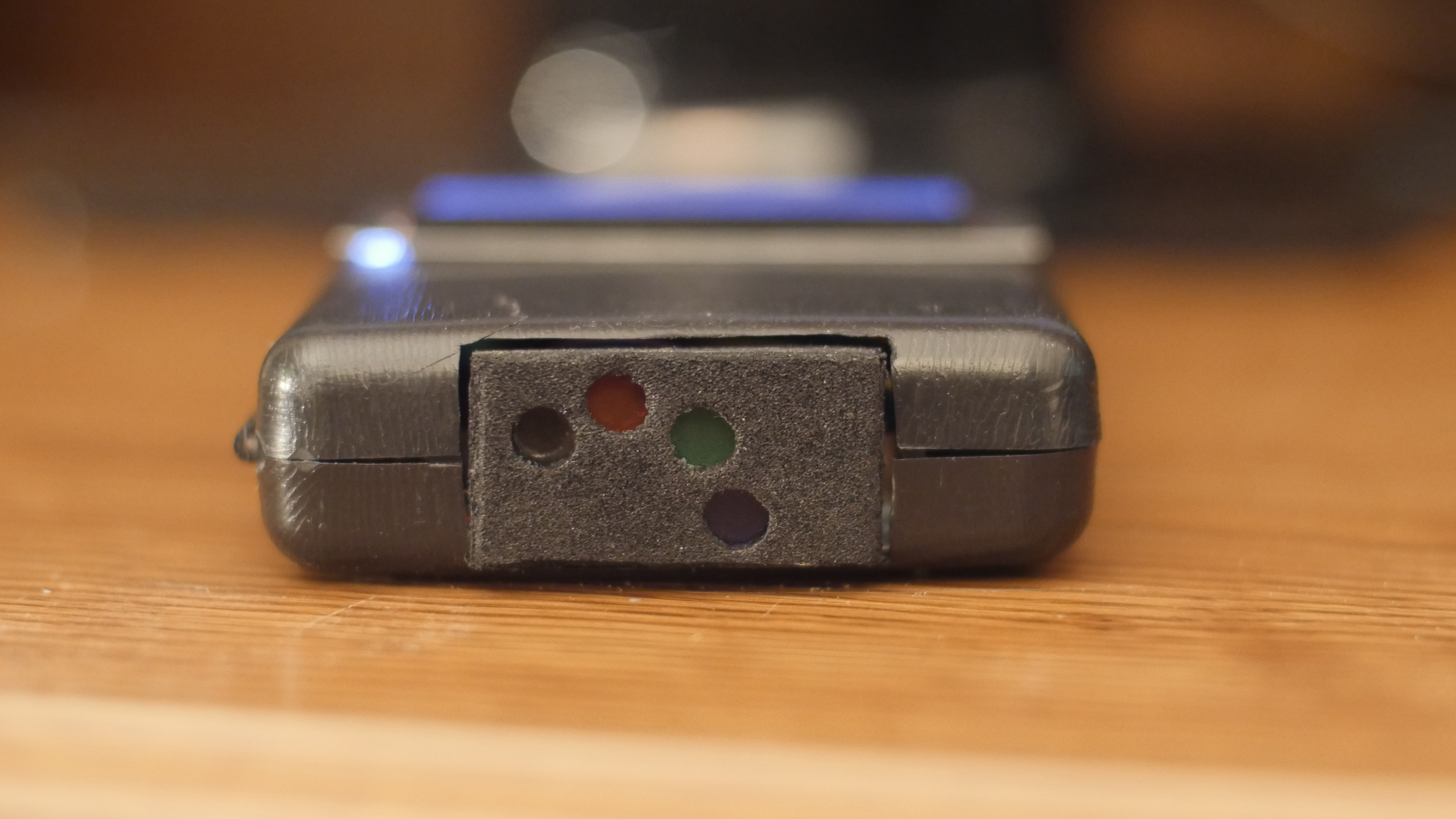
##The Sensor First I tackled the most import part, the sensor. I had some color gels used for camera lighting, I chose to use red, green, and blue (the additive primary colors) for even coverage across the color spectrum.
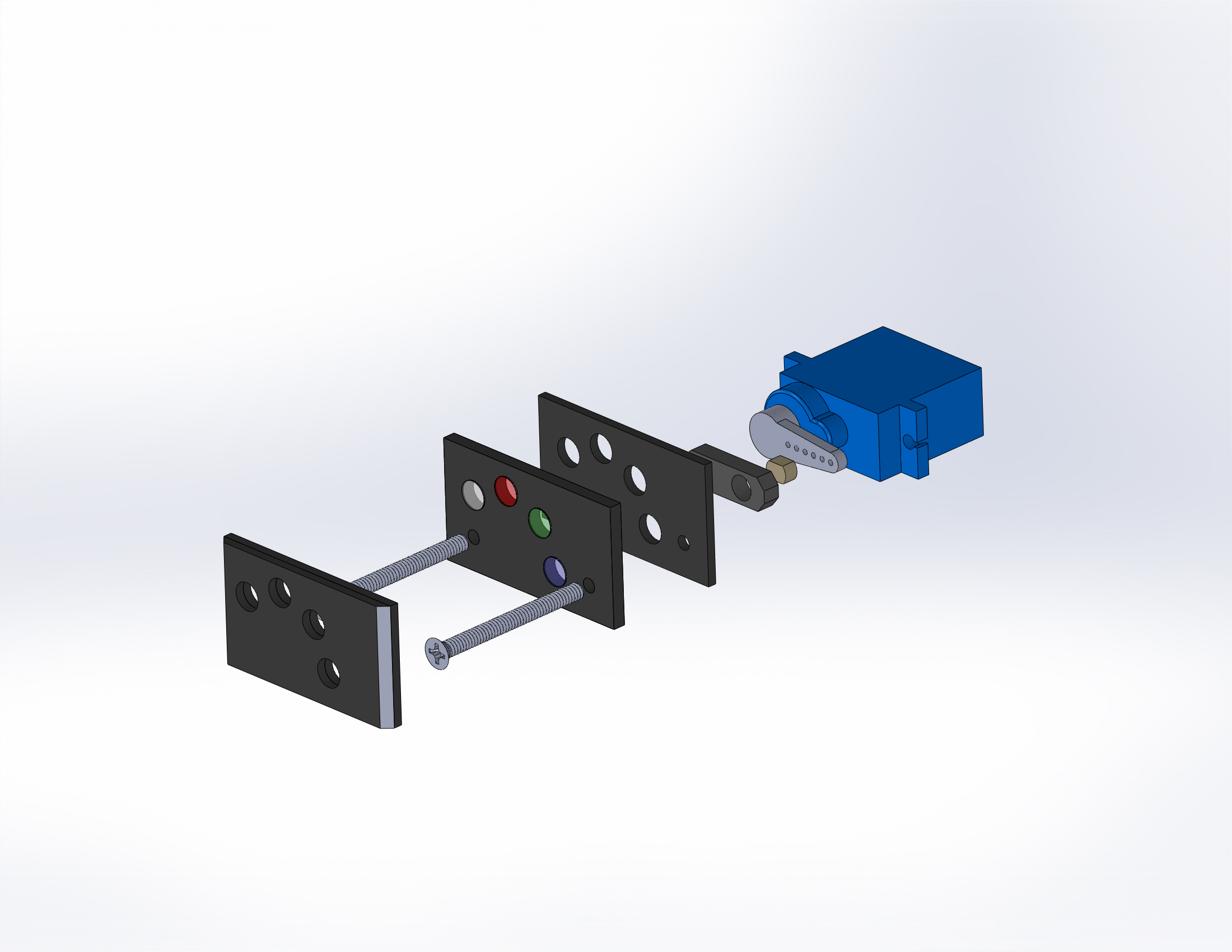
Unfortunately I only had one photo resistor so I used a servo to take measurements through each filter.
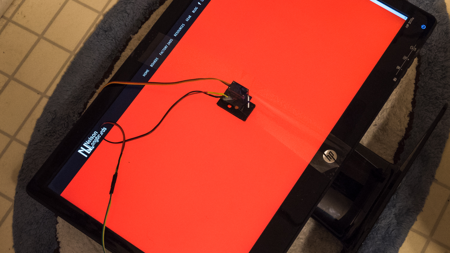
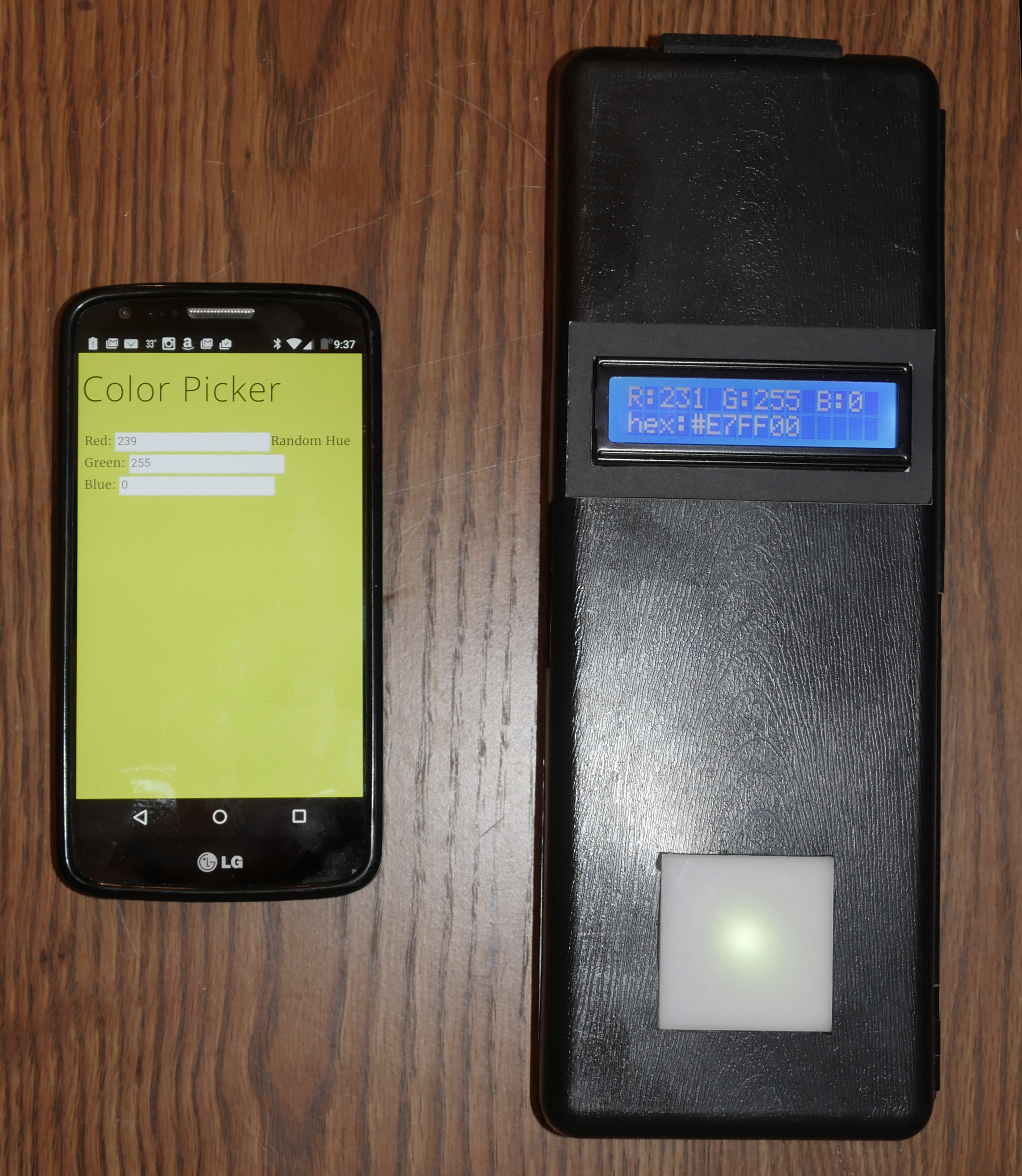
##Calibration After assembling the sensor and the next step was to collect test data for calibration. An Arduino was used to collect the analog light measurements form the photo resistor and to control the servo motor. I limited the scope to measuring hue, there are 1560 hues in the 24 bit RGB color system, I wrote this color picker web app in AngularJS, mounted the sensor onto a calibrated monitor, and setup a python script to iterate through the 1560 hues and record the readings.
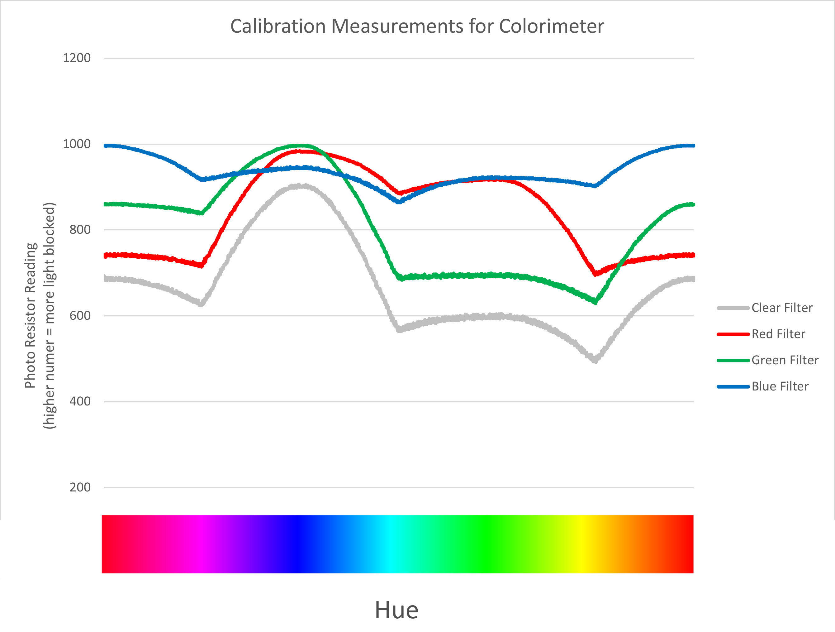
With a database of calibration measurements, we now have a set of known values to compare new measurements to in order to find the closest match.
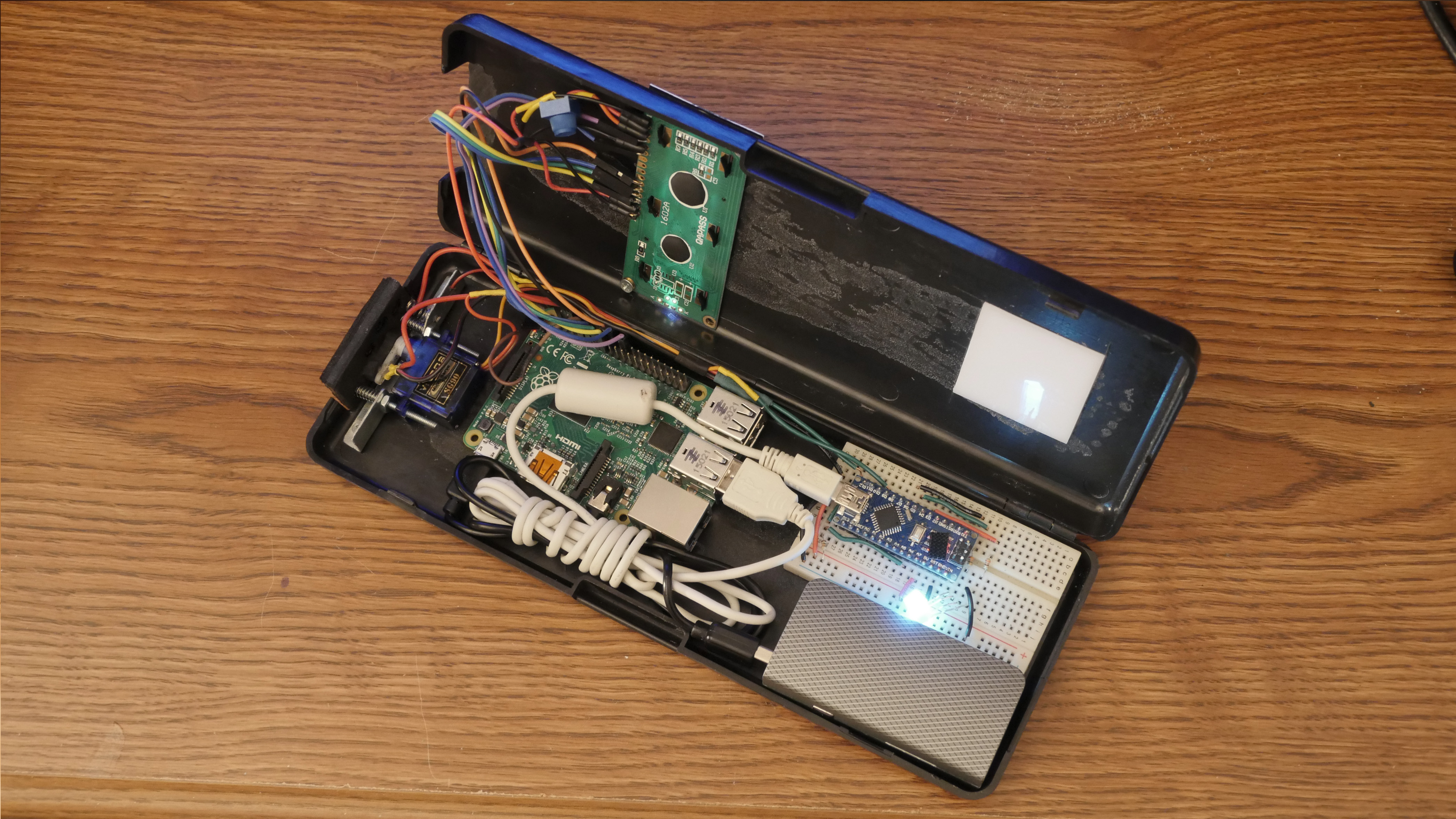
##Finishing Touches The last step was to create an interface and assemble all of the components into the case, for the “start button” I mounted the sensor on springs, with another spring and screw arranged so that a small amount of pressure on the front will make them touch and complete a circuit to trigger the measurement function. An LCD screen displays the RGB and hex values of the measured color, and an RGB led lights up in the measured color. After testing across 3 different screens that colorimeter is over 97% accurate.
##Colorimter Mark two update 3/7/16
Even though the first version worked well, there was definitely some room for improvement, the most obvious improvement would be eliminating the moving parts and having a sensor dedicated to each filter, but I still only have one photo sensor so I’m sticking with the rule of just using parts that I already own.
The focus focus of these improvement is to optimize the programming to eliminate unnecessary hardware. The original program referenced the entire database of calibration measurements when determining new colors, the database alone was about 45kb. So I did a polynomial regression analysis of the calibration measurements to establish a set of equations that can be used to determine colors.
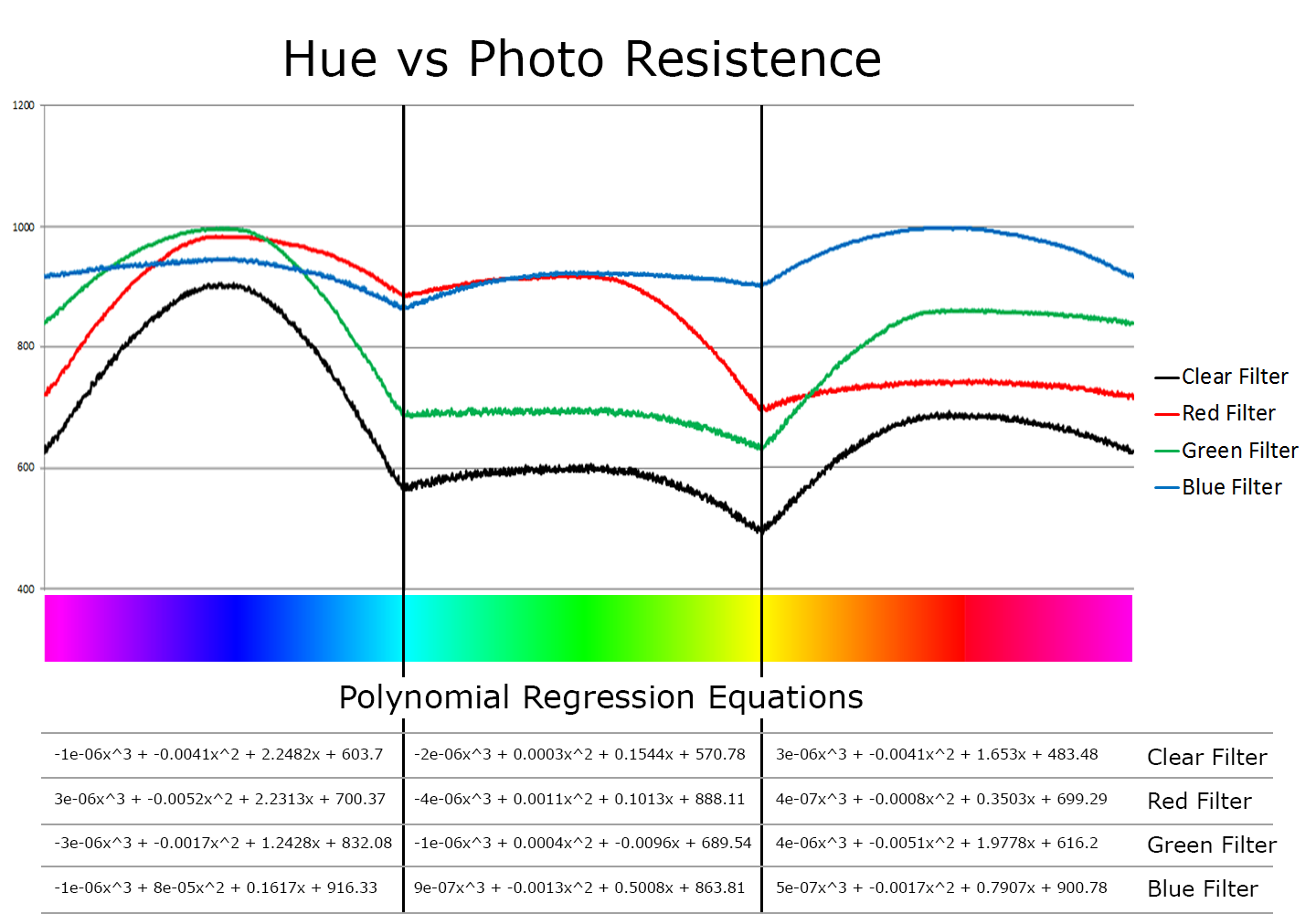
The data naturally split into three intervals each section spanning the range in which one of the primary color channels was at 100% or 255 in our 24 bit color system. After finding the representative 3rd order polynomial equations we no longer need the Raspberry Pi computer to do heavy lifting with the database, and the whole program will fit onto the 32kb of memory on the Arduino’s ATmega328 micro controller.
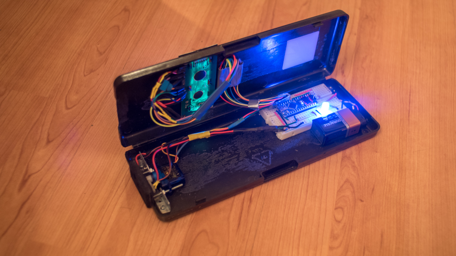
I rewrote the code to get everything running on the Arduino, Also ditching the USB power bank for a simple 9v battery. Ditching the two most expensive components brings the total cost of materials to about $10, not including the case. It also starts up much faster now, ready to measure within about 2 seconds of powering up. The accuracy seems to be about the same as before, but testing is required to compare. I’m considering making a new case for it, but if I do that I would probably want to get some more sensors to eliminate the need for the servo to make things more compact and reliable. also I saw 16x2 LCD screens online with an RGB backlight so the function of these screen and led could possibly be combined.